


Contents
- The principle of operation of shell-and-tube heat exchangers and their scope
- Calculation of the parameters of a shell-and-tube dephlegmator
- Design features of the shell-and-tube heat exchanger
- Calculation of parameters of a shell-and-tube cooler
- Drawings of shell-and-tube dephlegmators and refrigerators
- Afterword
The most common type of heat exchanger in industry is the shell-and-tube type. The variant of its design depends on the tasks facing users. The shell-and-tube does not have to be multi-pipe – an ordinary shirt reflux condenser, direct-flow (a) or counter-flow (b) pipe-in-pipe refrigerator are also shell-and-tubes.

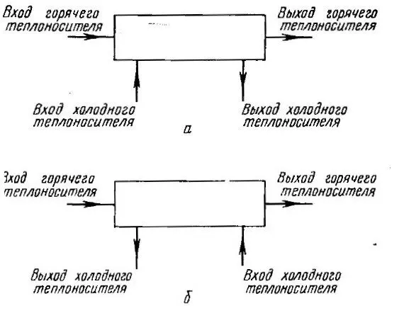
Single-pass heat exchangers with cross-flow movement of heat carriers are also used (c). But the most effective and often used for multi-pipe heat exchangers is the multi-pass cross-flow scheme (d).

With this scheme, one flow of liquid or vapor moves through the pipes, and the second coolant moves towards it in a zigzag manner, repeatedly crossing the pipes. This is a hybrid of counterflow and crossflow options, which allows you to make the heat exchanger as compact and efficient as possible.
The principle of operation of shell-and-tube heat exchangers and their scope
In moonshine brewing, multi-pass cross-flow refrigerators are commonly called shell-and-tube refrigerators (CCT), and their single-pipe version is called a counter- or direct-flow refrigerator. Accordingly, when using these structures as dephlegmators – shell-and-tube and jacket dephlegmators.
In home moonshine stills, mash and distillation columns, steam is supplied to these heat exchangers through internal pipes, and cooling water is supplied to the casing. Any industrial designer-heat engineer would be outraged, since it is in the pipes that a high coolant velocity can be created, significantly increasing the heat transfer and efficiency of the installation. However, distillers have their own goals and do not always need high efficiency.
For example, in dephlegmators for steam columns, on the contrary, it is required to soften the temperature gradient, spread the condensation zone as much as possible in height, and, having condensed the necessary part of the steam, prevent overcooling of the phlegm. Yes, and precisely regulate this process. Quite different criteria come to the fore.
Among the refrigerators used in moonshine brewing, the most widely used are coils, straight-throughs and shell-and-tubes. Each of them has its own area of use.
For devices with low (up to 1,5-2 l / h) productivity, the use of small flow coils is most rational. In the absence of running water, coils also give odds to other options. The classic version is a coil in a bucket of water. If there is a water supply system and the productivity of the device is up to 6-8 l / h, then direct-flow pipes designed according to the “pipe in pipe” principle, but with a very small annular gap (about 1-1,5 mm), have an advantage. A wire is spirally wound onto the steam pipe with a step of 2-3 cm, which centers the steam pipe and lengthens the path of the cooling water. With heating capacities up to 4-5 kW, this is the most economical option. A shell-and-tube can, of course, replace a straight-through, but the cost of manufacture and water consumption will be higher.
The shell and tube comes to the fore in autonomous cooling systems, since it is completely undemanding to water pressure. As a rule, a conventional aquarium pump is enough for successful operation. In addition, at heating powers of 5–6 kW and above, a shell-and-tube cooler becomes practically the only option, since the length of a once-through cooler for utilizing high powers will be irrational.


For reflux reflux columns, the situation is somewhat different. With small, up to 28-30 mm, diameters of the columns, the most rational is an ordinary shirt (in principle, the same shell-and-tube).
For diameters of 40-60 mm, the Dimroth dephlegmator becomes the leader. It is a high precision cooler with precise power control and absolute non-airing. Dimroth allows you to set modes with the least supercooling of phlegm. When working with packed columns, due to its design, it makes it possible to center the reflux return, irrigating the packing in the best possible way.
The shell and tube comes to the fore in autonomous cooling systems. Irrigation of the nozzle with reflux occurs not in the center of the column, but over the entire plane. This is less effective than Dimroth’s, but quite acceptable. The water consumption in this mode for the shell-and-tube will be significantly higher than for Dimroth.
If you need a condenser for a liquid extraction column, then Dimroth is unrivaled due to the accuracy of regulation and low reflux subcooling. A shell-and-tube is also used for this purpose, but phlegm hypothermia is difficult to avoid and water consumption will be higher.
The main reason for the popularity of shell-and-tubes with appliance manufacturers is that they are more versatile in use, and their parts are easily unified. In addition, the use of shell-and-tube dephlegmators in apparatuses of the “designer” or “changeling” type is unrivaled.
Calculation of the parameters of a shell-and-tube dephlegmator
The calculation of the required heat exchange area can be performed using a simplified method.
1. Determine the heat transfer coefficient.
| Name | Layer thickness h, m | Thermal conductivity λ, W / (m * K) | Thermal resistance R, (m2K) / W. |
| Metal-water contact zone (R1) | 0,00001 | ||
| Pipe metal (stainless steel λ=17, copper – 400), (R2) | 0,001 | 17 | 0,00006 |
| Phlegm (average film thickness in the condensation zone for a dephlegmator 0,5 mm, for a refrigerator – 0,8 mm), (R3) | 0,0005 | 1 | 0,0005 |
| Metal-steam contact zone, (R4) | 0,0001 | ||
| Total thermal resistance, (Rs) | 0,00067 | ||
| Heat transfer coefficient, (K) W / (m2TO) | 1493 |
Formulas for calculations:
R = h / λ, (m2 K) / W;
Rs = R1 + R2 + R3 + R4, (m2 K) / W;
K u1d 2 / Rs, W / (mXNUMX K).
2. Determine the average temperature difference between steam and cooling water.
The temperature of saturated alcohol vapor Tp = 78,15 °C.
The maximum power from the dephlegmator is needed in the mode of operation of the column on itself, which is accompanied by a maximum supply of water and its minimum temperature at the outlet. Therefore, we assume that the water temperature at the inlet to the shell-and-tube (15 – 20) – T1 = 20 ° C, at the outlet (25 – 40) – T2 = 30 ° C.
Tin = Tp – T1;
Tout u2d Tp – TXNUMX;
The average temperature (Тav) is calculated by the formula:
Tav = (Tin – Tout) / Ln (Tin / Tout).
That is, in our case rounded:
Tin = 58°C;
Tout = 48°C.
Тср = (58 — 48) / Ln (58 / 48) = 10 / Ln(1,21) = 53 °C.
3. Calculate the heat exchange area. Based on the known heat transfer coefficient (K) and the average temperature (Tav), we determine the required surface area for heat transfer (St) for the required heat output (N), W.
St = N / (Tsr * K), m2;
If we, for example, need to utilize 1800 W, then St = 1800 / (53 * 1493) = 0,0227 m2, or 227 cm2.
4. Geometric calculation. Decide on the minimum diameter of the tubes. In the dephlegmator, phlegm goes towards the steam, so it is necessary to meet the conditions for its free flow into the nozzle without excessive hypothermia. If you make tubes of too small diameter, you can provoke a choke or release of phlegm into the area above the reflux condenser and further into the selection, then you can simply forget about good purification from impurities.
The minimum total cross section of the tubes at a given power is calculated by the formula:
Cutter = N * 750 / V, mm2Where
N – power (kW);
750 – vaporization (cm3 / s kW);
V is the steam velocity (m/s);
Ssec – the minimum cross-sectional area of the tubes (mm2)
When calculating column-type distillers, the heating power is selected based on the maximum steam velocity in the column of 1-2 m/s. It is believed that if the speed exceeds 3 m / s, then the steam will drive the phlegm up the column and throw it into the selection.
If you need to dispose of in a dephlegmator 1,8 kW:
Ssec u1,8d 750 * 3 / 450 uXNUMXd XNUMX mm2.
If you make a reflux condenser with 3 tubes, then the cross-sectional area of u450bu3bone tube is not less than 150/XNUMX = XNUMX mm2, inner diameter – 13,8 mm. The nearest larger standard pipe size is 16 x 1 mm (14 mm inner diameter).
With a known pipe diameter d (cm), we find the minimum required total length:
L= Sт / (3,14 * d);
L= 227 / (3,14 * 1,6) = 45 cm.
If we make 3 tubes, then the length of the dephlegmator should be about 15 cm.
The length is adjusted taking into account that the distance between the partitions should approximately equal the inner radius of the hull. If the number of partitions is even, then the pipes for supplying and draining water will be on opposite sides, and if odd, on one side of the dephlegmator.
An increase or decrease in the length of pipes within the radius of domestic columns will not create problems with the controllability or power of the reflux condenser, as it corresponds to errors in the calculation and can be compensated for by further design solutions. You can consider options with 3, 5, 7 or more tubes, then choose the best one from your point of view.
Design features of the shell-and-tube heat exchanger

Partitions
The distance between the partitions is approximately equal to the radius of the body. The smaller this distance, the greater the flow velocity and the less the possibility of dead zones.
Baffles direct the flow across the tubes, this significantly increases the efficiency and power of the heat exchanger. Also, the baffles prevent the deflection of the tubes under the influence of thermal loads and increase the rigidity of the shell-and-tube dephlegmator.
Segments are cut out in the partitions for the passage of water. The segments must be no less than the cross-sectional area of the pipes for water supply. Usually this value is about 25-30% of the partition area. In any case, the segments must ensure the equality of the water velocity along the entire trajectory of movement, both in the tube bundle and in the gap between the bundle and the body.
For a reflux condenser, despite its small (150-200 mm) length, it makes sense to make several partitions. If their number is even, the fittings will be on opposite sides, if odd – on one side of the dephlegmator.
When installing transverse baffles, it is important to ensure that the gap between the housing and the baffle is as small as possible.
Tubes
The thickness of the walls of the tubes does not really matter. The difference in the heat transfer coefficient for a wall thickness of 0,5 and 1,5 mm is negligible. In fact, the tubes are thermally transparent. The choice between copper and stainless steel, in terms of thermal conductivity, also loses its meaning. When choosing, one must proceed from operational or technological properties.
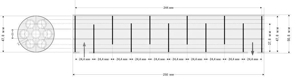
When marking the tube plate, they are guided by the fact that the distances between the axes of the tubes should be the same. Usually they are placed at the vertices and along the sides of a regular triangle or hexagon. According to these schemes, with the same pitch, it is possible to place the maximum number of tubes. The central tube most often becomes a problem if the distances between the tubes in the bundle are not the same.
The figure shows an example of the correct arrangement of the holes.

For the convenience of welding, the distance between the tubes should not be less than 3 mm. To ensure the strength of the joints, the material of the tube sheet must be harder than the material of the pipes, and the gap between the sheet and pipes should not exceed 1,5% of the pipe diameter.
When welding, the ends of the pipes should protrude above the grate by a distance equal to the wall thickness. In our examples – by 1 mm, this will allow you to make a high-quality seam by melting the pipe.
Calculation of parameters of a shell-and-tube cooler
The main difference between a shell-and-tube refrigerator and a reflux condenser is that the phlegm in the refrigerator flows in the same direction as the steam, so the phlegm layer in the condensation zone increases from the minimum to the maximum more smoothly, and its average thickness is somewhat larger.
For calculations, we recommend setting the thickness to 0,8 mm. In a dephlegmator, the opposite is true – at first, a thick layer of phlegm, which has merged from the entire surface, meets steam and practically prevents it from fully condensing. Then, having overcome this barrier, the vapor enters a zone with a minimum, about 0,5 mm thick, reflux film. This is the thickness at the level of its dynamic retention, condensation occurs mainly in this zone.

Taking the average thickness of the reflux layer equal to 0,8 mm, using a specific example, we will consider the features of calculating the parameters of a shell-and-tube cooler using a simplified method.
| Name | Layer thickness h, m | Thermal conductivity λ, W / (m * K) | Thermal resistance R, (m2K) / W. |
| Contact zone of metal with water, (R1) | 0,00001 | ||
| Pipe metal (stainless steel λ=17, copper – 400), (R2) | 0,001 | 17 | 0,00006 |
| Phlegm, (R3) | 0,0008 | 1 | 0,001 |
| Metal-steam contact zone, (R4) | 0,0001 | ||
| Total thermal resistance, (Rs) | 0,00117 | ||
| Heat transfer coefficient, (K) W / (m2TO) | 855,6 |
The maximum power requirements for the refrigerator are made by the first distillation, for which the calculation is made. Useful heating power – 4,5 kW. Water inlet temperature – 20 °C, outlet – 30 °C, steam – 92 °C.
Tin u92d 20 – 72 uXNUMXd XNUMX ° C;
Tout u92d 30 – 62 uXNUMXd XNUMX ° C;
Tsp = (72 – 62) / Ln (72/62) = 67 ° C.
Heat transfer area:
St u4500d 67 / (855,6 * 787) uXNUMXd XNUMX cm².
Minimum total cross-sectional area of pipes:
S section = 4.5 * 750/10 = 338 mm²;
We choose a 7-pipe refrigerator. Sectional area of one pipe: 338 / 7 = 48 mm or inner diameter 8 mm. From the standard range of pipes, 10×1 mm (with an internal diameter of 8 mm) is suitable.
Attention! When calculating the length of the refrigerator, an outer diameter of 10 mm is needed.
Determine the length of the refrigerator tubes:
L u787d 3,14 / 1 / 250 u250d 7 cm, therefore, the length of one tube: 36 / XNUMX uXNUMXd XNUMX cm.
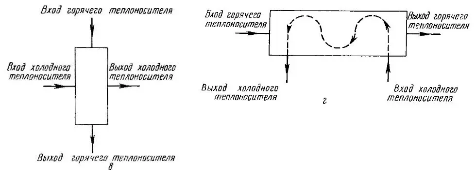
We clarify the length: if the refrigerator body is made of a pipe with an inner diameter of 50 mm, then there should be 25 mm between the partitions.
36 / 2,5 = 14,4.
Therefore, it is possible to make 14 partitions and get water input-output pipes in different directions, or 15 partitions and pipes will look in one direction, and the power will also increase slightly. We select 15 partitions and adjust the length of the tubes to 37,5 mm.
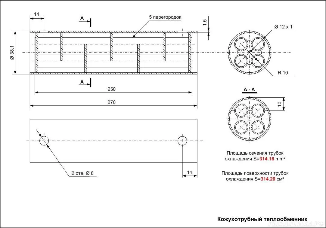
Drawings of shell-and-tube dephlegmators and refrigerators
Manufacturers are in no hurry to share their drawings of shell-and-tube heat exchangers, and home craftsmen do not really need them, but still some schemes are in the public domain.


Afterword
It should not be forgotten that all of the above is a theoretical calculation using a simplified method. Thermotechnical calculations are much more complicated, but in the real household range of changes in heating power and other parameters, the technique gives correct results.
In practice, the heat transfer coefficient may be different. For example, due to the increased roughness of the inner surface of the pipes, the phlegm layer will become higher than the calculated one, or the refrigerator will be located not vertically, but at an angle, which will change its characteristics. There are many options.
The calculation allows you to accurately determine the dimensions of the heat exchanger, check how the change in the diameter of the pipes will affect the characteristics and reject all unsuitable or guaranteed worst options without extra costs.
The author of the article is IgorGor.